Wiring Basics,
Identifying the Parts
Wiring
of the circuit could not be easier. As there are
only two components (three if you count the LED),
there is no need for circuit boards. Simply
solder the components together in a shape that
suits your locomotive. Please note the
orientation of the chip, as it must be wired one
way only. The LED must be wired the correct way
around too. To identify the correct polarity note
the following points:
| l |
The positive lead is usually
longer than the negative |
| l |
The flange around the base
of the LED is usually flattened just
above the negative lead. |
| l |
The negative lead usually
has the internal reflector attached to it
inside the LED. |
The resistor is not polarised and
can be wired either way around. Remember to
insulate the circuit from shorting against itself
or anything around it. This can be as simple as
wrapping the leads (once you have soldered them
together) with a small tab of scotch tape. The
most important note is that if the middle pin of
the chip shorts to the 3rd pin (i.e. across the
resistor) then the LED will most probably burn
out.
Wiring
Diagram
Please
note that the markings on your chip may well be
different than that shown above. It should say LM334Z
on it somewhere though. Make sure if you are
asking for (or ordering) it by name to add the Z
on the end, as the other versions are too big for
most model use. The Z version is the most common
and commercially available version.
While
the above diagram shows wire connecting the
individual part, you would not typical need wire
to connect in the resistor. Just solder the leads
directly together, it may benefit you to cut them
shorter before you do though.
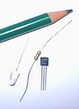
The
parts look like (with a pencil for scale):
Photo
of the Parts Involved
|