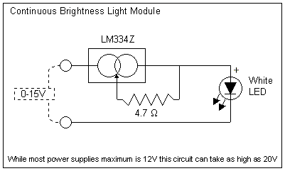
Circuit Details
The
LM334Z is a constant current source which
requires only a single resistor to set the
current. While the specifications for the chip
state that it is only programmable to a maximum
of 10mA, we will be running it at 15mA. This is
quite acceptable for our use, and we will not be
exceeding the units rated Power Dissipation of
400mW. The chip is wired completely inline with
the LED. One of the advantages to this design is
that you do not need different components to
drive different LEDs. The nature of the circuit
means that it will equally well drive a 1.7V Red
LED or a 3.6V White LED without any modification!
As the chip is completely protected by design
from reverse voltages up to 20V, we do not need
to add any reverse protection diodes (which drop
the voltage).
At
the level we will be using the chip it will not
even get warm. One thing to note is that the low
value of the resistor means that it is difficult
(if not impossible) to get in very accurate
tolerances. The resistor type is of the 5%
tolerance type, which means the value may
actually be 5% off from the specified value. This
would never cause concern, but it may be
beneficial to measure the resistor's resistance
with a multimeter and use the lowest value to
gain up to a couple milliamps in current if you
are trying to get the brightest light.
Circuit
Schematic

|
![]()
![]()